Friday, November 29, 2013

What really AC (Alternate Current) and Power are ?


You may face some confusion when reading AC (Alternate Current) things in basic Electronic or Electric writings. As unlike water current we cannot see actual movements of Electrical Current(s) we must believe what the writer says. But most writers of the writings on AC (Alternate Current) things are not quite sure of it by themselves, I assume, or taking it for granted (the readers already know it).

For instance

Ground and neutral - wiki

This article needs additional citations for verification. Please help improve this article by adding citations to reliable sources. Unsourced material may be challenged and removed. (September 2012) 


As the neutral point of an electrical supply system is often connected to earth ground, ground and neutral are closely related. Under certain conditions, a conductor used to connect to a system neutral is also used for grounding (earthing) of equipment and structures. Current carried on a grounding conductor can result in objectionable or dangerous voltages appearing on equipment enclosures, so the installation of grounding conductors and neutral conductors is carefully defined in electrical regulations. Where a neutral conductor is used also to connect equipment enclosures to earth, care must be taken that the neutral conductor never rises to a high voltage with respect to local ground.

Contents

Definitions

Ground or earth in a mains (AC power) electrical wiring system is a conductor that provides a low impedance path to the earth to prevent hazardous voltages from appearing on equipment (the terms "ground" (North American practice) and "earth" (most other English-speaking countries) are used synonymously here). Under normal conditions, a grounding conductor does not carry current.
Neutral is a circuit conductor that carries current in normal operation, which is connected to ground (or earth).
In a polyphase or three-wire (single-phase) AC system, the neutral conductor is intended to have similar voltages to each of the other circuit conductors. By this definition, a circuit must have at least three wires for one to serve as a neutral.

-----

Mains electricity - Wiki


Mains electricity is the general-purpose alternating-current (AC) electric power supply.
:
:

Building wiring

In most countries, household power is single-phase electric power, with two or three wired contacts at each outlet.
  • The live wire (also known as phase, hot or active contact), carries alternating current between the power grid and the household.
  • The neutral wire completes the electrical circuit by also carrying alternating current between the power grid and the household. The neutral is connected to the ground, and therefore has nearly the same electrical potential as the earth. This prevents the power circuits from increasing beyond earth voltage, such as when they are struck by lightning or become otherwise charged.
  • The earth wire or ground connects the chassis of equipment to earth ground as a protection against faults (electric shock), such as if the insulation on a "hot" wire becomes damaged and the bare wire comes into contact with the metal chassis or case of the equipment.

----

Wiki itself notices that the above two articles are not good stuff. Let us take some better descriptions.

From: http://www.dummies.com/how-to/content/alternating-current-in-electronics-hot-neutral-and.html

Alternating Current in Electronics: Hot, Neutral, and Ground Wires

Before you start working with line voltage in your electronic circuits, you need to understand a few details about how most residential and commercial buildings are wired. The following description applies only to the United States; if you’re in a different country, you’ll need to determine the standards for your country’s wiring.
Standard line voltage wiring in the United States is done with plastic-sheathed cables, which usually have three conductors. This type of cable is technically called NMB cable, but most electricians refer to it using its most popular brand name, Romex.
image0.jpg Two of the conductors in NMB cable are covered with plastic insulation (one white, the other black). The third conductor is bare copper. These conductors are designated as follows:
  • Hot: The black wire is the hot wire, which provides a 120 VAC current source.
  • Neutral: The white wire is called the neutral wire. It provides the return path for the current provided by the hot wire. The neutral wire is connected to an earth ground.
  • Ground: The bare wire is called the ground wire. Like the neutral wire, the ground wire is also connected to an earth ground. However, the neutral and ground wires serve two distinct purposes.
    The neutral wire forms a part of the live circuit along with the hot wire. In contrast, the ground wire is connected to any metal parts in an appliance such as a microwave oven or coffee pot. This is a safety feature, in case the hot or neutral wires somehow come in contact with metal parts.
    Connecting the metal parts to earth ground eliminates the shock hazard in the event of a short circuit.
Note that some circuits require a fourth conductor. When a fourth conductor is used, it's covered with red insulation and is also a hot wire.
The three wires in a standard NMB cable are connected to the three prongs of a standard electrical outlet (properly called a receptacle). As you can see, the neutral and hot wires are connected to the two vertical prongs at the top of the receptacle (neutral on the left, hot on the right) and the ground wire is connected to the round prong at the bottom of the receptacle.
image1.jpg You can plug a two-prong or three-prong plug into a standard three-prong receptacle. Two-prong plugs are designed for appliances that don't require grounding.
Most nongrounded appliances are double-insulated, which means that there are two layers of insulation between any live wires and any metal parts within the appliance. The first layer is the insulation on the wire itself; the second is usually in the form of a plastic case that isolates the live wiring from other metal parts.
Three-prong plugs are for appliances that require the ground connection for safety. Most appliances that use a metal chassis require a separate ground connection.
There is only one way to insert a three-prong plug into a three-prong receptacle. But regular two-prong plugs, which lack the ground prong, can be connected with either prong on the hot side.
To prevent that from happening, the receptacles are polarized, which means that the neutral prong is wider than the hot prong. Thus, there's only one way to plug a polarized plug into a polarized receptacle. That way, you can always keep track of which wire is hot and which is neutral.

-----

The underlines made by me.

  • Hot: The black wire is the hot wire, which provides a 120 VAC current source.
  • Neutral: The white wire is called the neutral wire. It provides the return path for the current provided by the hot wire. The neutral wire is connected to an earth ground.

These explanations on AC (as we are not talking about Ground so I omit it ) are very common. You can find them through internet easily. You will try as I did.

But when you consider the AC (Alternate Current) nature it is very strange that <the hot wire, which provides a 120 VAC current (source)> and < the neutral wire. It provides the return path for the current provided by the hot wire.> as AC changes its direction with time regularly (sinusoidouslly) as the rate of 50/60Hz / second. So what do <xxx provides a 120 VAC current (source)> and <xxx return path for the current> mean? If we talk about DC sourced by a battery (batteries) the explanation seems more reasonable as DC has only one fixed direction all the time.

Let's be back to very basic things.

From: http://hyperphysics.phy-astr.gsu.edu/hbase/electric/hsehld.html

Household Wiring


The standard U.S. household wiring design has two 120 volt "hot" wires and a neutral which is at ground potential. The two 120 volt wires are obtained by grounding the center tap of the transformer supplying the house so that when one hot wire is swinging positive with respect to ground, the other is swinging negative. This versatile design allows the use of either hot wire to supply the standard 120 volt household circuits. For higher power applications like clothes dryers, electric ranges, air conditioners, etc. , both hot wires can be used to produce a 240 volt circuit.

-----

Please read the above explanation and see carefully the transformer part.


Center Tap (Transformer) - Wiki 
:
:
: 
Common applications of center-tapped transformers


  • A full-wave rectifier using two diodes and a center tap transformer.

    The above is the typical rectifier circuit by using center-tapped transformer.

    The sine wave is misleading as the horizontal line is time, If you think the place at the top of the secondary winding, at the left side of D1 the voltage change 0 -> + peak -> 0 and then -> - peak -> 0 periodically.

    Meanwhile If you think the place at the bottom of the secondary winding, at the left side of D2 the voltage change 0 -> - peak -> 0 and then -> + peak -> 0 periodically.
    Then the above right hand picture showing the upper part of hr sine waves .

     
    We neglect the two diodes and get


Please regard 120V as 240V and 60V as 120V (actually any voltages will do for principal explanation as far as the ratio is correct. And then think about the only one circuit the (2nd winding) upper line (as hot wire) and the center tap wire (as the neutral wire) and neglect the lower line (hot line) shown in the above drawing of hyperphysics as well.

We then consider the resistor as the resistance value of the the whole system of the right hand side. This whole system may consist of several actual Resistors, Capacitors, Inductors, Diodes, Transistor, ICs, etc and consume Electrical Power (Energy) to do something for you. Now we consider the power consumed by this one system Resistor.

Power = I x V
                                                                                                               
You may know that in terms of Power AC or DC does not matter as
P = I^2 R = \frac{V^2}{R},


Next, or I would like to say "finally", you think about what is happening on the upper and center tap points of the secondary winding of the transformer. Again we cannot see them (can see by using oscilloscope but still this is not really happening there as the horizontal line of the oscilloscope screen is time) but guess it. It may not be the current "provided" (pushed out) at the point of upper point and not "return" (pulled in, pushed in) at the point of the center tap continuously as the current is AC = Alternate Current.

Still a big question remains - how actually and exactly Electrical Energy is transferred from a power station to a household in a big picture and how Energy (reached a household) is transferred from the inlet to the power consuming home appliance(s) in a small picture? Either in a big picture or small picture the basic behavior of Electric Energy may be the same.


ACT


Friday, June 21, 2013

Reciprocal


Reciprocal is somehow anti-intuitive. y = x is a very simple function, a simple straight line but its reciprocal : y = 1/x is not simple at all as shown below.

(Note: y = 1/x. This can be changed to yx = 1. also think of a rectangular having area 1 (fixed) and one side y , the other side x. Think about the meaning of this.)


Ohm's Law

         V
I =  ------
         R (in Ohm)


Ohm's Law shows a simple relation between I (current), V(voltage) and R(Resistance). When V is fixed, the relation between I and R becomes simply reciprocal. Say, to make V = 1 (volt), it becomes

         1
I =  ------
         R


When R is very large, say 1M ohm ( 1,000,000 ohm) and 1G ohm (1,000,000, 000 ohm), the current differs very little from 1/1,000,0000 A (1uA) to 1/1,000,000,000 (1 nano A), much less than 1mA and much far less than 1A. Analogically if you a resistor your effort to increase from 1M ohm to 1G ohm (1,000 times higher) will very little rewarded as the current decreases only by 1 / 1000 or 0.999 uA.

On the other hand,  when R is small (not very small), say from 1 ohm to 0.1 ohm (differs only 0.9 ohm), the current changes from 1A to 10A (fairy large current). If  R is 0.1 Ohm and  0.01 Ohm, the difference is only 0.09 Ohm but the current increases from 10A to 100A (huge current), which will make a common consumer use battery die in a very short period. Again analogically if you a resistor and you decrease (yourself) from 1 ohm to 0.01 ohm (only by 0.99 ohm) you will get a big reward of 100A from 1A.

This relates with the following fundamentally very important relation is

\int {1 \over x}\,dx=\ln \left|x\right|+C

Ref

y = sin (1/x)

The graph of this relation becomes

Picture 1

Copy from https://samjshah.com/2009/10/03/sin1x/

This article is easy to read.

The sine function has the max value 1 (one) and the minimum value is -1 (minus one) but the cycle becomes extremely frequent as x reaches 0 (zero), which the chart cannot show.

<to becomes extremely frequent>can be expressed as <to become more frequent exponentially>. Reciprocal and exponential may have some relations.


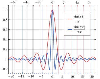
Looks similar but different - sinc function (wiki)


{\displaystyle \operatorname {sinc} (x)={\frac {\sin(x)}{x}}.}


Another Ref


R, C, L Circuits

In Parallel Circuit of Resistors and Inductors (Coils) and the Series Circuit of Capacitors we can find reciprocals. Simple one is a Parallel Circuit of Resistors. The conclusion is

The Reciprocal of the total resistance = the sum of the Reciprocal of each Resistance.


Generally 

IT  =  I1 + I2 + I3.

I = V/R

Therefore

VT/RT  =  V1/R1 + V2/R2 + V3/R3

Since VT =  V1 = V2 = V3

Therefore 1/RT  = 1/R1 + 1/R2 + 1/R3

Intuitively to bundle or twist the three wires together more current flows in them than the current flow in one single wire. But why <The Reciprocal of the total resistance = the sum of the Reciprocal of each Resistance> ?  we need the above calculation. And remember <The total resistance is not the sum of the Reciprocal of each Resistance> but <The Reciprocal of the total resistance is the sum of the Reciprocal of each Resistance>, I would say double Reciprocal.

Not RT  = 1/1 Ohm + 1/10 Ohm  + 1/100 Ohm   = 111/100 Ohm

But 

1/RT  = 1/1 Ohm + 1/10 Ohm  + 1/100 Ohm   = 111/100 Ohm

RT  = 100/111 Ohm  (Less than 100 Ohm)

I would say "Double Reciprocal " as  we usually calculate like

                        1
RT  =   -----------------------------
              1/R1 + 1/R2 + 1/R3

And I think many people do this though some strangeness remains.
 

Contrary to the Parallel arrangement Series Circuit is straight forward or very simple. The total Resistance = the sum of each Resistance.


R = R1 + R2 + R3 + ...


Generally 

VT  = V1 + V2 +V3.

IR = V

Therefore

ITRT  =  I1R1 + I2R2 + I3R3

Since IT =  I1 = I2 = I3


Therefore  RT  = R1 + R2 + R3


Inductors act like resistors as XL (which is regarded as resistance) = 2πfL. On the other and Capacitors act as reciprocal of Resistors as XC (which is regarded as resistance) = 1/2πfC. 


More interesting reciprocal nature will be found in the combination of  RC, RL, LC and LCR Circuits, which I will review later.


ACT

Monday, April 29, 2013

Angular frequency ω (which is equal to 2πf)


A part of the explanation of "AC current" of wiki (as of 29-April-2013) is as follows:


"
Mathematics of AC voltages

Alternating currents are accompanied (or caused) by alternating voltages. An AC voltage v can be described mathematically as a function of time by the following equation:
v(t)=V_\mathrm{peak}\cdot\sin(\omega t),
where
  • \displaystyle V_{\rm peak} is the peak voltage (unit: volt),
  • \displaystyle\omega is the angular frequency (unit: radians per second)
    • The angular frequency is related to the physical frequency, \displaystyle f (unit = hertz), which represents the number of cycles per second, by the equation \displaystyle\omega = 2\pi f.
  • \displaystyle t is the time (unit: second).
 "
The title of wiki is "AC current" but Mathematics is about "AC voltage", which is not a big issue and you can change the voltage to the current (I) - i(t) = Ipeak x sin (ωt).

The relation between ω (angular frequency) and f ("physical" or "ordinary" frequency) is stated above. Then, what is the difference between ω and f ?

A part of the explanation of "Angular frequency" of wiki (as of 29-April-2013) is as follows:

"
One revolution is equal to 2π radians, hence[1][2]
\omega = {{2 \pi} \over T} = {2 \pi f} ,
where
ω is the angular frequency or angular speed (measured in radians per second),
T is the period (measured in seconds),
f is the ordinary frequency (measured in hertz) (sometimes symbolised with ν),

Units

In SI units, angular frequency is normally presented in radians per second, even when it does not express a rotational value. From the perspective of dimensional analysis, the unit Hertz (Hz) is also correct, but in practice it is only used for ordinary frequency f, and almost never for ω. This convention helps avoid confusion.[3] 

 "

Well the same thing except it says <From the perspective of dimensional analysis, the unit Herz (Hz) is also correct>.  The relation between ω (angular frequency) and f ("ordinary" frequency) is stated above. Then, again, what is the difference between ω and f ?


                                                     Number
Frequency (f) is simply ----------------------------------------------  .  and concerns
                                   Unit time (usually second in Electronics)

about the number of cycles and does not concern about the content of one cycle. It simply shows "how many times the same thing happens per unit time, say per second" or " how frequently the same thing happens per unit time (per second)." So it applies cycles other than sinusoidal cycles.


Meanwhile Capative Reactance and Inductive Reactance are expressed as follow:

Capacitive reactance
X_C = \frac {1} {\omega C} = \frac {1} {2\pi f C}
Inductive reactance
X_L = \omega L = 2\pi f L

As far as <the unit Herz (Hz) is also correct>without mathematical rigor or even being incorrect for the sake of simplicity or conceptual understanding, why not

            1
Xc = -------       and    
XL = fL

           fC


In case of very low frequency like one (1) cycle  per 10 seconds or 1/10 cycle per second, 2π does matter - - 2π (2 x 3.14 = 6.28) /0.1 = 62.8.  But in case of high frequency like 1MHz (1,000,000 cycles per second), 2π does not make much difference comparatively (in ohm) - 2π (2 x 3.14 = 6.28) /1,000,000 = 0.00000628. 2π factor contributing to the reactance is large at very low frequencies while almost negligible at high frequencies. What does matter is just frequency ("how frequently he same thing happens per unit time). Meanwhile common capacitors range from 10pF to some thousand µF (the unit of C in the above formulas is F) Farad and common inductors ranges 10µH to some hundred mH (the unit of L in the above formulas is Henry).

ACT

Wednesday, January 23, 2013

RC time constant - conceptual undertanding


Time Constant of a simple RC circuit (RC are connected in series) is R (in Ohm) x C (in Farad). The wiki 's explanation of  "RC time constant" is very simple.

"
The RC time constant, the time constant (in seconds) of an RC circuit, is equal to the product of the circuit resistance (in ohms) and the circuit capacitance (in farads), i.e. \tau = R × C.
It is the time required to charge or discharge the capacitor, through the resistor, by ≈ 63.2 percent of the difference between the initial value and final value. This value is derived from the mathematical constant e, specifically 1-e^{-1}.
 "
However, wiki explains it further in more broadly in "Time constant". Time constant is universal not limited to electric/electronic circuits. Generally "Time constant" is defined as

 "
Physically, the constant represents the time it takes the system's step response to reach 1-1/e \approx 63.2\,\% of its final (asymptotic = infinitely close to a certain) value. In radioactive decay the time constant is called the decay constant (λ), and it represents both the mean lifetime of a decaying system (such as an atom) before it decays, or the time it takes for all but 36.8% of the atoms to decay. For this reason, the time constant is longer than the half-life, which is the time for only 50% of the atoms to decay. (wiki: Time Constant)
"
Here " step response" is

"step response" is the time behavior of the outputs of a general system when its inputs change from zero to one in a very short time. The concept can be extended to the abstract mathematical notion of a dynamical system using an evolution parameter. (wiki: Step Response)
"

Now we think about "RC time constant" in somehow different ways from the most text books.

1. The unit of Time Constant (usually denoted by \tau ) is second (or time) as the name shows where as decay constant (usually denoted by λ) is 1/sec (or 1/ time). So " t / λ" is just number, no unit. So e-t/RC  makes sense, no unit, where RC = \tau.


2. The unit of RC

The unit of RC is second (or time). See below (wiki: Ohm and Farad).


\Omega = \dfrac{\mbox{V}}{\mbox{A}} = \dfrac{\mbox{m}^2 \cdot \mbox{kg}}{\mbox{s} \cdot \mbox{C}^2} = \dfrac{\mbox{J}}{\mbox{s} \cdot \mbox{A}^2}=\dfrac{\mbox{kg}\cdot\mbox{m}^2}{\mbox{s}^3 \cdot \mbox{A}^2}= \dfrac{\mbox{J} \cdot \mbox{s}}{\mbox{C}^2} = \dfrac{\mbox{1}}{\mbox{S}}

in which the following units appear: volt (V), ampere (A), siemens (S), watt (W), second (s), joule (J), coulomb (C), kilogram (kg), and meter (m). 
 
Please do not confuse siemens (S) with second (s)


\mbox{F}
= \,\mathrm{\frac{A \cdot s}{V}
= \dfrac{\mbox{J}}{\mbox{V}^2}
= \dfrac{\mbox{W} \cdot \mbox{s}}{\mbox{V}^2}
= \dfrac{\mbox{C}}{\mbox{V}}
= \dfrac{\mbox{C}^2}{\mbox{J}}
= \dfrac{\mbox{C}^2}{\mbox{N} \cdot \mbox{m}}
= \dfrac{\mbox{s}^2 \cdot \mbox{C}^2}{\mbox{m}^{2} \cdot \mbox{kg}}
= \dfrac{\mbox{s}^4 \cdot \mbox{A}^2}{\mbox{m}^{2} \cdot \mbox{kg}}
= \dfrac{\mbox{s}}{\Omega}}

The unit of <RC time constant>, as the name suggests, is s = second (time)

R : unit Ω (Ohm)
C : unit F (Farad)

so unit wise, by using the above unit formulas

RC: ΩF: Ω x s/Ω = s, or (s/F) x F = s

This is a bit strange and anti-tuition

3. Why e ?

Natural response (wiki: RC Circuit)

The simplest RC circuit is a capacitor and a resistor in series. When a circuit consists of only a charged capacitor and a resistor, the capacitor will discharge its stored energy through the resistor.


The voltage across the capacitor, which is time dependent, can be found by using Kirchhoff's current law, where the current through the capacitor must equal the current through the resistor.

 (the same current runs through each element (current is a through variable): ir (in) = ic (out) although the current value changes with time or dynamically)

This results in the linear differential equation
C\frac{dV}{dt} + \frac{V}{R}=0.
Solving this equation for V yields the formula for exponential decay:  (*)
V(t)=V_0 e^{-\frac{t}{RC}} \ ,
where V0 is the capacitor voltage at time t = 0.

The time required for the voltage to fall to \frac{V_0}{e} is called the RC time constant and is given by

\tau = RC \ .


(*) You need some knowledge of solving this differential equation. See below.


Exponential decay (wiki)


A quantity undergoing exponential decay. Larger decay constants make the quantity vanish much more rapidly. This plot shows decay for decay constants of 25, 5, 1, 1/5, and 1/25 for x from 0 to 5.


A quantity is subject to exponential decay if it decreases at a rate proportional to its value. Symbolically, this process can be expressed by the following differential equation, where N is the quantity and λ (lambda) is a positive number called the decay constant:
\frac{dN}{dt} = -\lambda N.
(My note:  The underlined parts are key. Exponential, either positive (growth) or negative (decay) has this nature. (Ref: ttp://betterexplained.com/articles/an-intuitive-guide-to-exponential-functions-e/)
Also note that N should be N (t), which value changes with time, dynamical changes)

The solution to this equation (see Solution of the differential equation below) is: Exponential rate of change
N(t) = N_0 e^{-\lambda t}. \,

Here N(t) is the quantity at time t, and N0 = N(0) is the initial quantity, i.e. the quantity at time t = 0.


------
Solution of the differential equation The equation that describes exponential decay is


or, by rearranging with respect time (t),


 Integrating, we have


(**) 

( N should be N (t) ) where C is the constant of integration, and hence


 where the final substitution, N0 = eC, is obtained by evaluating the equation at t = 0, as N0 is defined as being the quantity at t = 0.
                                                      

This is the form of the equation that is most commonly used to describe exponential decay. Any one of decay constant, mean lifetime, or half-life is sufficient to characterise the decay.

(**) Again you need some knowledge of integration. See below.

Right hand side:


dN(t)     1
----  =   ----- d N(t)
N (t)     N (t)


The integrating the right hand side it becomes

ln N(t) + C

as


Then take exponential the both sides becomes


as

   ln N(t)
e            = N(t)  


You must understand this. This seems tricky but this comes from the following definition or the inverse of this.
ln ex = x

-----

Now back to the above result - RC time constant:
 

where V0 is the capacitor voltage at time t = 0.

The time required for the voltage to fall to is called the RC time constant and is given by


Relations between Capacitor Voltage, Capacitor Charge and Resistor current (or more generally the circuit current). Please note that the relation between Capacitor Voltage and Resistor Voltage is Vr+Vc=0 or Vr=-Vc.

Chart form Hyperphysics


Examples

When R = 1 Ohm and C = 1F, or more realistically R = 1K Ohm and C = 1000uF (1F/1,000) or R = 1M Ohm and C = 1uF (1F/1,000,000), RC = 1 (sec).

So t/RC --> 1 (sec)/ 1(sec) = 1 (no unit), then

V(1) = Vo / e ---> Vo / 0.3686...

Of course it is not necessary to be 1 and usually not 1. When R = 1K Ohm and C = 1000uF then RC = 1 /1000 (sec), very short period. Then

V(0.001) = Vo / e ---> Vo / 0.3686...

The original question in here is <Why e ?>.

The answer is that this is a natural phenomenon. The nature has been made this way or God made it this way. Shall we leave science?

What is the cause of this rate, exp (-1) or 1 / e is made? It mat relate more with a function of capacitor, not resistor (which does not include differentiation itself). It may relate with how (in terns of time) a capacitor is charged and discharged. Discharge may be a reverse or inverse case of being charged. It is unrealistic to start with an already charged capacitor and it may be less difficult to think how a capacitor is charged and then reverse or inverse it to a case of being discharged. To do this we must add a battery to the above simple circuit.


From wiki: RC Circuit
These equations are for calculating the voltage across the capacitor and resistor respectively while the capacitor is charging; for discharging, the equations are vice-versa. These equations can be rewritten in terms of charge and current using the relationships C=Q/V and V=IR (see Ohm's law).


Thus, the voltage across the capacitor tends towards V as time passes, while the voltage across the resistor tends towards 0, as shown in the figures. This is in keeping with the intuitive point that the capacitor will be charging from the supply voltage as time passes, and will eventually be fully charged.
These equations show that a series RC circuit has a time constant, usually denoted being the time it takes the voltage across the component to either rise (across C) or fall (across R) to within of its final value. That is, is the time it takes to reach and to reach .


The rate of change is a fractional per . Thus, in going from to 

, the voltage will have moved about 63.2% of the way from its level at toward its final value. So C will be charged to about 63.2% after , and essentially fully charged (99.3%) after about . When the voltage source is replaced with a short-circuit, with C fully charged, the voltage across C drops exponentially with t from towards 0. C will be discharged to about 36.8% after , and essentially fully discharged (0.7%) after about . Note that the current, , in the circuit behaves as the voltage across R does, via Ohm's Law.


These results may also be derived by solving the differential equations describing the circuit:


and


. The first equation is solved by using an integrating factor and the second follows easily


Capacitor voltage step-response.


Resistor voltage step-response.

Chart form Hyperphysics


Charging a Capacitor When a battery is connected to a series resistor and capacitor, the initial current is high as the battery transports charge from one plate of the capacitor to the other. The charging current asymptotically approaches zero as the capacitor becomes charged up to the battery voltage. Charging the capacitor stores energy in the electric field between the capacitor plates. The rate of charging is typically described in terms of a time constant RC.

-------

Now we think about <the voltage will have moved about 63.2% of the way from its level at toward its final value. So C will be charged to about 63.2% after >.

When there is no charge on the capacitor plates charges will be built up quickly after the the battery voltage applied and the current starts to flow. As time passes more and more charges exist and therefore voltage become being built up on the plates but at the rate of


As time passes once charges (voltage) built up they tend to resist against further building up of new charges (voltage) so the the rate of building up slows down again at the rate of


because less and less space for charges (geometrically in 2D and 3D) or some other force (physically, chemically, etc) or say voltage against further building up of charges become stronger and stronger (higher and higher for voltage). The voltage relates as CV= Q (charge) or


where C is constant (-> Capacitance, sptt)

Now how about in case of being discharged. Discharging quickly at fast and then slowly at the rate of


This may be because that in the beginning many charges leave away from the plate quickly (due to higher voltage) once the exit wide open (short) and the time passes less and less charges (lower voltage) leave away from the plates. Or the magnitude of some force (say voltage like and relate with the number of the charges on the plates) which pushes the charges on the plates away from the plates becomes less and less strong as time passes.
Again the voltage relates as CV= Q (charge) or

Re-written in 2023.

ACT