Any Capacitor specification shows tan δ, or DF (Dissipation Factor).
1) Ceramic Capacitors
Murata GRM Series (Standard MLCC SMT type)
a) Temperature Compensation type
GRM1555C1H102JA01_(1005M(0402), C0G(EIA), 1000pF, DC 50V)
Q or Dissipation Factor (D.F):. Q≧1000 (that is DF = 1/1000 = 0.001)
Measurement Frequency1.0+/-0.1MHz, Measurement Voltage 0.5 to 5.0Vrms
b) High dielectric type
GRM155R71H104KE14_(1005M(0402), X7R(EIA), 0.1uF, DC 50V)
Q or Dissipation Factor (D.F.): DF≦0.1
Measurement Frequency1.0+/-0.1kHz
Measurement Voltage 1.0+/-0.2Vrms
The other brands' DFs are more or less the same.
2) Film Capacitor
a) Metallized Polyester (PET) Capacitor
RCQE (B) Series, DC use
Dissipation Factor (tan δ) tan δ ≦1.0% 20˚C 1kHz
b) Metallized Polypropylene Capacitor
ECWH (V) Series, DC use
Dissipation Factor (tan δ) tan δ ≦0.1% 20˚C 1KHz, tan δ ≦0.2% 20˚C 10KHz
The other brands' DFs are more or less the same.
3) Aluminum Electrolytic Capacitors
Nichicon UPW Series (Standard Radial Lead type)
Tangent of loss angle (tan δ)
For capacitance of more than 1000µF, add 0.02 for every increase of 1000µF. Measurement frequency : 120Hz at 20˚C
Rated voltage (V) T 6.3 10 16 25 35
50 63 100 160 to 250 315, 350 400, 450
Tangent of loss angle (tan δ) 0.22 0.19 0.16
0.14 0.12 0.10 0.09 0.08 0.15 0.20 0.25
The other brand specs are more or less the same.
Notes:
1) Measurement shows <frequency> but does not show voltage.
2) For capacitance of more than 1000µF, add 0.02 for every increase of 1000µF.
This relates
R
tanδ = ------ = ωCR
Xc
If you are not familiar with ω
ω = 2πf (*)
Therefore
C = Capacitance
R = ESR (Equivalent Series Resistance). Internal resistance of capacitor. Generally not desirable.
This formula will be explained later.
3) The above table shows
Lower voltages and higher voltages, tan δ high and middle voltage tan δ low. There must be some reasons but I never encounter a explanation. Tan δ or DF of Aluminum Electrolytic Capacitors are remarkably high as compared with Ceramic Capacitors and Film Capacitors.
The measuring frequency120Hz is lower than 1KHz (Ceramic and Film Capacitors) while Capacitances of Aluminum Electrolytic Capacitors are lager.
Electronic text books or manufacturer's Use Guides show usually a chart and calculation formula of tan δ or DF. But not easy to understand fully tan δ.or DF
ESR.
DF is rather simple. The ratio of ESR to Xc or --------
Xc
This is a simple proportional equation. ESR being constant, the larger Xc the smaller the smaller DF. The smaller Xc the larger DF.
As
R
tanδ (DF) = ------ = 2πfCR
Xc
and
 (you will see this later)
then, ESR being constant, the larger 2πfC, the smaller Xc, and then the larger DF. The smaller 2πfC, the larger Xc, and then the smaller DF.
tan δ is a bit complicated but the almost same thing. See below.

This chart or similar one is commonly seen in Electronics text books or manufacturer's Use Guide.
To understand this we must know Impedance of the above Impedance plane. The diagonal and the longest arrow is impedance.
Wiki
"
impedance is the opposition to alternating current presented by the combined effect of resistance and reactance in a circuit.
(ACT Opposing the current is resistance or creating something against the voltage change.
v
i = -----
r (ESR + Xc) --- Opposing the current )
Quantitatively, the impedance of a two-terminal circuit element is the ratio of the complex representation of the sinusoidal voltage between its terminals, to the complex representation of the current flowing through it. In general, it depends upon the frequency of the sinusoidal voltage.
Impedance can be represented as a complex number, with the same unit as resistance, for which the SI unit is the ohm (Ω).
Its symbol is usually Z, and it may be represented by writing its magnitude and phase in the polar form |Z|∠θ. However, Cartesian complex number representation is often more powerful for circuit analysis purposes.

l
l Omitted
l
Resistance and reactance together determine the magnitude and phase of the impedance through the following relations:

"
Notes:
Please do not confuse θ with δ.
arctan is inverse trigonometric function
that is
| arctangent | y = arctan(x) | x = tan(y) |
|---|
tan θ = X/R
(tan δ. = R/X)
We do not talk about Impedance further here
R is Resistive, Opposing the current resistively by generating heat (loss of energy to the outside)
X is Reactive, Opposing the current reactively, no loss of energy to the outside, keeping energy inside.
(wiki)
the impedance of a two-terminal circuit element is the ratio of the complex representation of the sinusoidal voltage between its terminals, to the complex representation of the current flowing through it.
"
the ratio of the voltage to the current is
in a simple DC case
V V
----- = R, I = -------
I R
This R (Resistance) does not change, ie constant.
This is Ohm's Law. This Ohm's Law can be applied to In AC (Alternate Current) circuit. Bu in more complicated ways.
Capacitive Reactance
Wiki
"
A capacitor consists of two conductors separated by an insulator, also known as a dielectric.
Capacitive reactance is an opposition to the change of voltage across an element. Capacitive reactance 


There are two choices in the literature for defining reactance for a capacitor. One is to use a uniform notion of reactance as the imaginary part of impedance, in which case the reactance of a capacitor is the negative number,
Another choice is to define capacitive reactance as a positive number,
.
In this case however one needs to remember to add a negative sign for the impedance of a capacitor, i.e. 
At 


The application of a DC voltage across a capacitor causes positive charge to accumulate on one side and negative charge to accumulate on the other side; the electric field due to the accumulated charge is the source of the opposition to the current. When the potential associated with the charge exactly balances the applied voltage, the current goes to zero.
Hyper Physics
"
Charging a Capacitor
When a battery is connected to a series resistor and capacitor, the initial current is high as the battery transports charge from one plate of the capacitor to the other. The charging current asymptotically approaches zero as the capacitor becomes charged up to the battery voltage. Charging the capacitor stores energy in the electric field between the capacitor plates. The rate of charging is typically described in terms of a time constant RC.

"
(ACT : RC = Time Constant and the unit is second,. But forget about this here. Just mind the curve of the charging current, which decreases with time and the increment or increasing ratio of Q amount which decreases with time.
Also the important thing (not mentioned here) is that when the switch is on a large current flows to against the change of the voltage. The voltage on a capacitor tries to the maximum, the source (battery) voltage, instantly but this is prohibited by a large current flow, actually the accumulation of charges on a capacitor. This is <an opposition to the change of voltage across an element.> This is the point.
In case of AC, the voltage of the source changes constantly, regularly, sinusoidally, but the principal of the current flow on a capacitor against the change of the voltage reamins the same.)
Wiki (continued)
Driven by an AC supply (ideal AC current source), a capacitor will only accumulate a limited amount of charge before the potential difference changes polarity and the charge is returned to the source. The higher the frequency, the less charge will accumulate and the smaller the opposition to the current.
"
The last part relates with
<f> increases and Xc deceases.
It dos not explain why when <C> increases Xc deceases. But analogously This is because a larger capacitance accumulates less charges per unit area, and the smaller the opposition to the current.
to oppose the change in voltage leads to the opposition to the current.
The red italic parts may be wrong.
Another explanation.-1
"
"
Analogously
the larger the capacitance, the more charges accumulated in a capacitor, the more current will flow. Likewise,the smaller the capacitance, the less charges accumulated in a capacitor, the the current will flow.
-------
Another explanation -2
"
ALL ABOUT CIRCUITS
Capacitors Vs. Resistors
Capacitors do not behave the same as resistors. Whereas resistors allow a flow of electrons through them directly proportional to the voltage drop, capacitors oppose changes in voltage by drawing or supplying current as they charge or discharge to the new voltage level.
The flow of electrons “through” a capacitor is directly proportional to the rate of change of voltage across the capacitor. This opposition to voltage change is another form of reactance, but one that is precisely opposite to the kind exhibited by inductors.
(ACT. Voltage drop:
Wiki
Voltage drop is the decrease of electric potential along the path of a current flowing in a circuit. (Wik)
In case of DC
V = IR (the voltage of a device, capacitor, simple device)
V becomes equal to the source voltage when fully charged. Voltage built-up but called 'voltage drop'. And no more current flow.
In case of AC
V = I Z (the voltage of a device, capacitor)
"
AC voltages additionally have a second kind of opposition to current flow: reactance. The sum of resistance and reactance is called impedance.
Electrical impedance is commonly represented by the variable Z and measured in ohms at a specific frequency. Electrical impedance is computed as the vector sum of electrical resistance, capacitive reactance.
The amount of impedance in an alternating-current circuit depends
on the frequency of the alternating current.
Analogous to Ohm's law for direct-current circuits, electrical impedance may be expressed by the formula E (V) = I Z. So, the voltage drop in an AC circuit is the product of the current and the impedance of the circuit. (Wiki)
"
Back to ALL ABOUT CIRCUITS
Capacitor Circuit Characteristics
Expressed mathematically, the relationship between the current “through” the capacitor and rate of voltage change across the capacitor is as such:
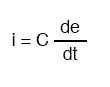
The expression de/dt is one from calculus, meaning the rate of change of instantaneous voltage (e) over time, in volts per second. The capacitance (C) is in Farads, and the instantaneous current (i), of course, is in amps.
Sometimes you will find the rate of instantaneous voltage change over time expressed as dv/dt instead of de/dt: using the lower-case letter “v” instead or “e” to represent voltage, but it means the exact same thing. To show what happens with alternating current, let’s analyze a simple capacitor circuit:
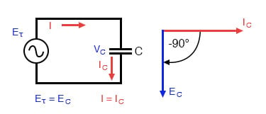
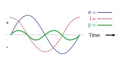
Pure capacitive circuit: capacitor voltage lags capacitor current by 90°
If we were to plot the current and voltage for this very simple circuit, it would look something like this:
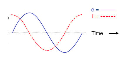
Pure capacitive circuit waveforms.
Remember, the current through a capacitor is a reaction against the change in voltage across it.
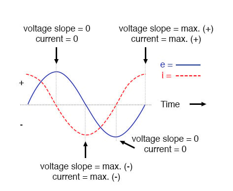
Therefore, the instantaneous current is zero whenever the instantaneous voltage is at a peak (zero change, or level slope, on the voltage sine wave), and the instantaneous current is at a peak wherever the instantaneous voltage is at maximum change (the points of steepest slope on the voltage wave, where it crosses the zero line).
(ACT: This part may relates with <capacitors oppose changes in voltage by drawing or supplying current as they charge or discharge to the new voltage level.).
This results in a voltage wave that is -90° out of phase with the current wave. Looking at the graph, the current wave seems to have a “head start” on the voltage wave; the current “leads” the voltage, and the voltage “lags” behind the current.
Voltage lags current by 90° in a pure capacitive circuit.
( ACT: Remind the phenomenon of capacitors oppose changes in voltage by drawing or supplying current as they charge or discharge to the new voltage level.
Voltage slope (instantaneous change) = 0
Current = 0 (no need to react against the change of voltage)
Voltage slope (instantaneous change) = max (ー)
Current = max (ー) (max effort to react against the change of voltage)
Voltage slope (instantaneous change) = max (+)
Current = max (+) (max effort to react against the change of voltage)
At the other points, according to the sinusoidal instantaneous change of the voltage)
<capacitors oppose changes in voltage> reminds me of inertia -a tendency to do nothing or to remain unchanged.)
In a pure capacitive circuit, the instantaneous power may be positive or negative.
the 90-degree phase shift between voltage and current results in a power wave that alternates equally between positive and negative. This means that a capacitor does not dissipate power as it reacts against changes in voltage; it merely absorbs and releases power, alternately.
A Capacitor’s Reactance
A capacitor’s opposition to change in voltage translates to an opposition to alternating voltage in general, which is by definition always changing in instantaneous magnitude and direction.
For any given magnitude of AC voltage at a given frequency, a capacitor of given size will “conduct” a certain magnitude of AC current.
Just as the current through a resistor is a function of the voltage across the resistor and the resistance offered by the resistor, the AC current through a capacitor is a function of the AC voltage across it, and the reactance offered by the capacitor.
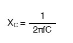
the reactance of a capacitor is expressed in ohms and symbolized by the letter X (or XC to be more specific).
Since capacitors “conduct” current in proportion to the rate of voltage change, they will pass more current for faster-changing voltages (as they charge and discharge to the same voltage peaks in less time), and less current for slower-changing voltages.
What this means is that reactance in ohms for any capacitor is inversely proportional to the frequency of the alternating current.
:"
Another simple explanation -3
DC. Source Voltage being constant
V
I = -------
R
Capacitor does not flow the current. R is infinitely large.
AC and only Xc is considered. Source Voltage changing up and down. Capacitor Voltage changing up and down. Capacitor current changing up and down accordingly with a phase shift.
v
i = ------- = v x 2πfC
Xc
i (current) increases when f (frequency) increases and / or Capacitance increases
Back to tan δ or DF, this is a ratio of ESR to Xc
ESR.
DF is rather simple. The ratio of ESR to Xc or --------
Xc
Therefore, even though Xc may change, the higher ESR the higher DF.
Wiki
Angular frequency can be obtained multiplying rotational frequency, ν (or ordinary frequency, f) by a full turn (2π radians): ω = 2π rad⋅ν.
2π radians = 2π x radius = one circumference
Ref
Post: Capacitance and Inductance as Inertia
F = ma
This can be rearranged as F/m = a. So m can be considered as against acceleration, which means against the change of velocity.
Capacitor analogy

CV = Q (cv = q)
Q/C = V (q/v = v)